Plot No. 253, Upper Ground Floor, Vill. Saidulajab, Saket, South Delhi, New Delhi - 110030.
Loading
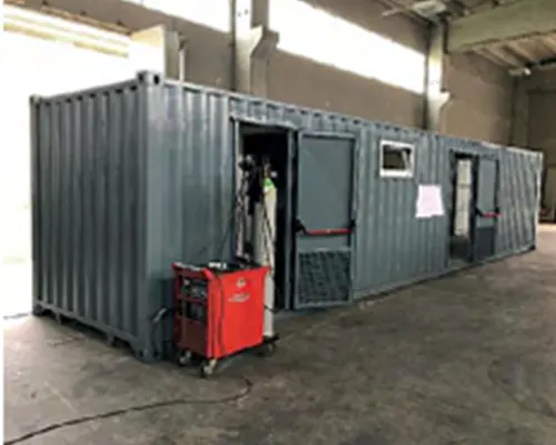
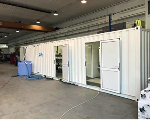
EMS Water Technology FWCP series containerized drinking water systems are de- signed to produce safe drinking water from freshwater sources, including those with high turbidity. They are ideal for the treatment of river water with high turbidity as is the case in Africa during the rainy season. The containerized drinking water plants EMS Water Technology FWCP series are housed in modified and recertified transport con- tainers and are therefore easily transportable. They can also be supplied with traditio- nal or alternative energy sources such as generators, photovoltaic or wind systems thus making the plants completely independent
Operation :- The containerized drinking water systems EMS Water Technology FWCP series are complete with chemical dosing system, lamellar pack settler, lifting pumps, sand filters, sludge dewatering units and electrical control panel. The unit can be supplied with a wide range of additional equipment and accessories such as drinking water tanks, distribution system, water supply pipes and if necessary drinking water distribution fountains. The containerized drinking water systemsb EMS Water Technology FWCP series are available in four standard modules , however the system is completely modular, so it is possible to satisfy a wide range of hydraulic flow rates
| TECHNICAL DATA | UNIT OF MEASURE | FWP® 10 | FWP® 20 | FWP® 40 | FWP® 100 |
|---|---|---|---|---|---|
| Raw (feed) water | m³/hr | 10 | 20 | 40 | 100 |
| Drinking water flow rate (others available upon request) | m³/hr | 10 | 20 | 40 | 100 |
| Hours of operation | hr/day | 8–24 | 8–24 | 8–24 | 8–24 |
| Daily production (based on hours of operation) | m³/day | 80–240 | 160–480 | 320–960 | 800–2,400 |
| People served per day (assuming 25 L/person/day) | ppl/day | 3,200–9,600 | 6,400–19,200 | 12,800–38,400 | 32,000–96,000 |
| Number of containers (for transport and housing) | n. | 1×20’ | 1×40’ | 1×40’ | 2×40’ |
| Installed power (excluding water intake pump) | kW | 5–6 kW 400V 50Hz | 11–12 kW 400V 50Hz | 14–15 kW 400V 50Hz | 25–30 kW 400V 50Hz |
| DESCRIPTION | FWP® 10 | FWP® 20 | FWP® 40 | FWP® 100 |
|---|---|---|---|---|
| Spare parts and consumables kits (1, 2 or 3-year supply) | ✓ | ✓ | ✓ | ✓ |
| Lifetime spare parts and consumables | ✓ | ✓ | ✓ | ✓ |
| Chemicals, cleaning and conservation products (kits) | ✓ | ✓ | ✓ | ✓ |
| Water intake pump with floatation device | ✓ | ✓ | ✓ | ✓ |
| Raw and treated water storage tanks (various types) | ✓ | ✓ | ✓ | ✓ |
| Photovoltaic system | ✓ | ✓ | ✓ | ✓ |
| Training on-site or in Euro Mec facilities | ✓ | ✓ | ✓ | ✓ |
| User and O&M manuals in languages other than Eng./Italian | ✓ | ✓ | ✓ | ✓ |
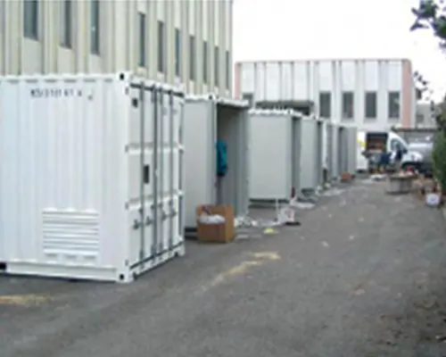
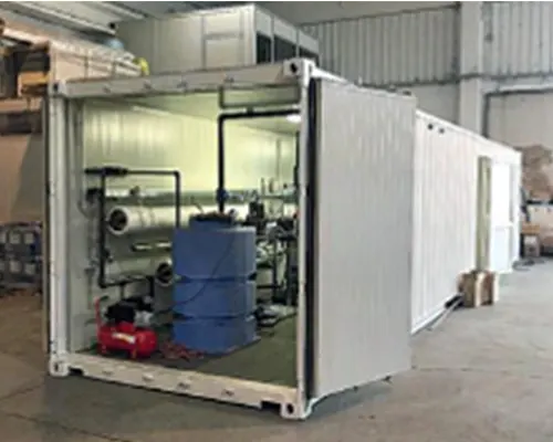
EMS Water Technology FWCP series containerized drinking water systems are de- signed to produce safe drinking water from freshwater sources, including those with high turbidity. They are ideal for the treatment of river water with high turbidity as is the case in Africa during the rainy season. The containerized drinking water plants EMS Water Technology FWCP series are housed in modified and recertified transport con- tainers and are therefore easily transportable. They can also be supplied with traditio- nal or alternative energy sources such as generators, photovoltaic or wind systems thus making the plants completely independent
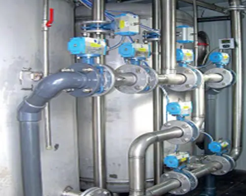
Operation :- TThe heart of the water treatment system is reverse osmosis and is designed to treat raw water from a range of conventional and unconventional sources in order to produce high purity drinking water. •Submersible electric pump with flexible system supply pipe. •Pre-treatment and prefiltration of raw water. •Reverse osmosis unit RO. •Post mineralization and disinfection treatment. •PLC electrical control panel with remote control system via GSM

| TECHNICAL DATA | |||
|---|---|---|---|
| TECHNICAL DATA | BWRO 100 | BWRO 240 | BWRO 360 |
| Capacity | 5 m³/hr | 8,33 m³/hr | 12,5 m³/hr |
| Production | 40 – 120 m³/day | 64 – 200 m³/day | 96 – 300 m³/day |
| Hours of operation | 8 – 24 hrs/day | 8 – 24 hrs/day | 8 – 24 hrs/day |
| Daily consumption (drinking only) | 25 litres per capita | 25 litres per capita | 25 litres per capita |
| People served | 1,600 – 4,800 / day | 2,560 – 7,680 / day | 3,840 – 11,520 / day |
| Effective salinity | < 2000 TDS | < 2000 TDS | < 2000 TDS |
| Treated water salinity | < 500 TDS | < 500 TDS | < 500 TDS |
| Power generator | 44 kVA | 52 kVA | 65 kVA |
| SPARE PARTS AND ACCESSORIES (✓ = Available) | |||
|---|---|---|---|
| DESCRIPTION | BWRO 100 | BWRO 240 | BWRO 360 |
| Street taps (drinking fountains) | ✓ | ✓ | ✓ |
| Spare parts and consumables kits (1, 2 or 3+ years supply) | ✓ | ✓ | ✓ |
| Lifetime spare parts and consumables | ✓ | ✓ | ✓ |
| Chemicals, cleaning and conservation products (kits) | ✓ | ✓ | ✓ |
| Remineralization system | ✓ | ✓ | ✓ |
| Raw and treated water storage tanks (various types) | ✓ | ✓ | ✓ |
| Photovoltaic system | ✓ | ✓ | ✓ |
| Training on-site or in EMS facilities | ✓ | ✓ | ✓ |
| User and O&M manuals in languages other than English/Italian | ✓ | ✓ | ✓ |
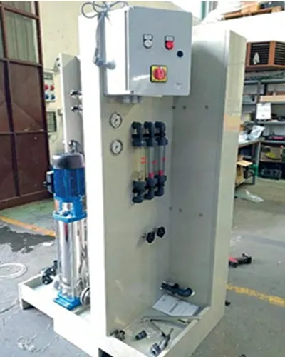
Description Osmosis is a natural process by which a more diluted solution spontaneously passes to a more concentrated solution through a semipermeable membrane. The concept of reverse osmosis is simple, as it is enough to apply pressure to a concentrated solution higher than the osmotic pressure to cause a reverse flow to the natural one, extracting the dissolved salts from the concentrated solution that manages a discharge flow; doing so on the other side of the membrane you have a low salinity solution
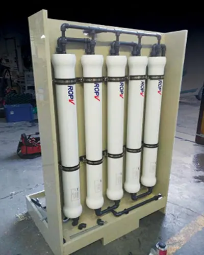
Operation :- The reverse osmosis system basically consists of a pressurization pump and a variable number of osmotic membranes depending on the flow rate and characteristics to be obtained; for this reason it is a reliable type of system and can operate continuously without the need of regeneration or washing. The operation of the system is managed automatically by a control panel sometimes preceded by a pre-treatment also mana- ged automatically.
| TECHNICAL DATA | ||||||||
|---|---|---|---|---|---|---|---|---|
| MODEL PLANT | UNITS OF MEASURE | M15 | M30 | M50 | M100 | M150 | M200 | M300 |
| Feeding salinity | Mg/l | < 2000 | < 2000 | < 2000 | < 2000 | < 2000 | < 2000 | < 2000 |
| Temperature | °C | 25 | 25 | 25 | 25 | 25 | 25 | 25 |
| Salinity across permeated | % | 1 | 1 | 1 | 1 | 1 | 1 | 1 |
| Standard capacity | Mc/h | 0.15 | 0.3 | 0.5 | 1 | 1.5 | 2 | 3 |
| Recovery max. | % | 35–50 | 52–70 | 35–50 | 52–70 | 62–76 | 68–76 | 76 |
| Vessel quantity | n. | 2 | 4 | 2 | 4 | 2 | 3 | 5 |
| Membrane quantity | n. | 2 | 4 | 2 | 4 | 6 | 9 | 15 |
| High pressure pump power | kW | 0.6 | 0.8 | 1.5 | 2.2 | 2.2 | 3.0 | 4.0 |
| Connection intake / perm | DN | 15,15,15 | 15,15,15 | 25,15,15 | 25,15,15 | 32,25,25 | 32,25,25 | 32,25,25 |
| DIMENSIONS AND WEIGHT | ||||||||
|---|---|---|---|---|---|---|---|---|
| PLANT MODEL | UNITS OF MEASURE | M15 | M30 | M50 | M100 | M150 | M200 | M300 |
| Dimensions (L×W×H) | m | 0.8×0.8×1.5 | 0.8×0.8×1.5 | 0.8×0.8×1.5 | 0.8×0.8×1.5 | 3.5×1×1.5 | 3.5×1×1.5 | 3.5×1×1.5 |
| Approximate weight | kg | 80 | 100 | 150 | 180 | 300 | 350 | 400 |
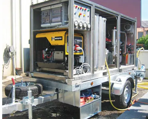
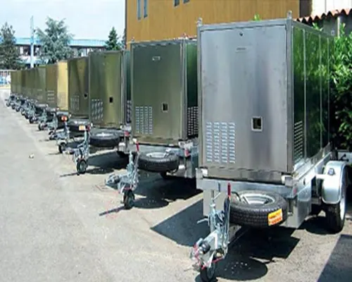
Description The COMBI BW/SWRO plant is designed and built by EMS Water Technology to pro- duce drinking water from the well, river, lake or sea in areas with very limited water resources. The mobility of the trailer on which the unit is mounted also makes it ide- al for emergency interventions as may be necessary following natural disasters or in camps for displaced people. Alternatively, these units may be part of the furniture or temporary camps of water supply systems for workplaces, missions, villages and their extended communities. The COMBI BW/SWRO can be easily transported by a wide range of vehicles and than- ks to a supplied generator it is completely autonomous once it arrives near a water source. The power of the current generator has been designed to have in addition to the availability of water also the necessary electricity for other uses such as night lighting and hence the name of COMBI = POWER+ H2O
Operation :- The COMBI BW/SWRO system is easy to use and has been designed to minimize the use of chemicals without compromising their performance. At the heart of the machi- ne is the reverse osmosis (RO) complete system of pressure pumps and osmosis mem- branes specifically selected according to the quality and quantity of water needed. The COMBI BW/SWRO is a very reliable unit capable of continuous operation without requiring maintenance or cleaning. The unit is managed automatically through a con- trol panel and, if necessary, they can also pre-treatment, also managed automatically.
| TECHNICAL DATA | ||
|---|---|---|
| TECHNICAL DATA | COMBI TRAILER BW | COMBI TRAILER SW |
| Raw water origin | Brackish water | Sea water |
| Drinking water TDS level (depending on salinity) | 0.5 – 15 m³/hr max | 0.5 – 15 m³/hr max |
| Working environment temperature | 5°C – 50°C | 5°C – 50°C |
| Installed power of the power generator | 5 kVA – 380V 50Hz | 10 kVA – 380V 50Hz |
| Power required | 300W – 380V 50Hz | 9kW – 380V 50Hz |
| Dimensions | 1140 × 2850 × 1400 mm | 1140 × 2850 × 1400 mm |
| Total weight (including generator) | 800 kg | 900 kg |
| SPARE PARTS AND ACCESSORIES (✓ = Available) | ||
|---|---|---|
| DESCRIPTION | COMBI TRAILER BW | COMBI TRAILER SW |
| Spare parts and consumables kits | ✓ | ✓ |
| Chemicals, cleaning and storage (kit) | ✓ | ✓ |
| Trailer | ✓ | ✓ |
| Trailer with NATO attachment, height adjustable | ✓ | ✓ |
| Final remineralization of water | ✓ | ✓ |
| Flotation device for the suction pump | ✓ | ✓ |
| Treated water storage tanks | ✓ | ✓ |
| Photovoltaic | ✓ | ✓ |
| Formation on-site on EMS Water Technology | ✓ | ✓ |
| User manuals and O&M in different languages (English / Italian) | ✓ | ✓ |

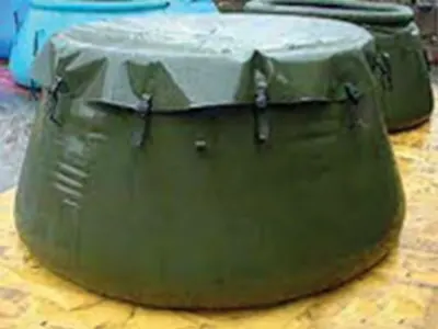
In the management of water emergencies it is necessary to use special flexible tanks for the accumulation of drinking water. EMS Water Technology has a complete series of transportable tanks with a volume of 1,000 0 12,000 lt. The packaging material is IN P. V.C non-toxic food and is treated to be insensitisable to ultraviolet rays. The flexible tan- ks are complete with outlet nozzle with exclusion valve and vent valve with overflow.
Operation :- For the collection of raw water can be conveniently used the “ onion “ tanks that have the characteristic of being self-supporting and ready for use without steel support structures.
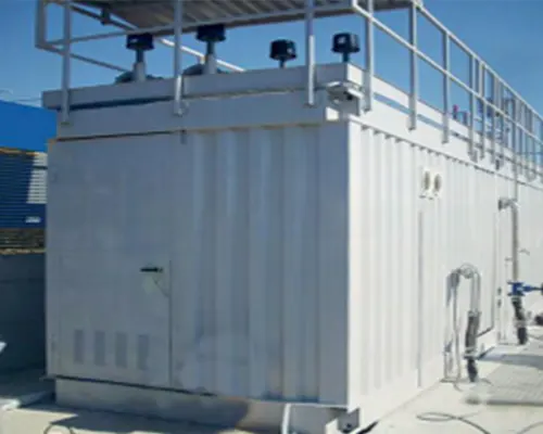
The containerized drinking water systems EMS Water Technology SWRO series are designed to desalinate bacteriologically and organoleptically polluted seawater, with a high salinity of 35,000 - 45,000 TDS. The high-pressure reverse osmosis system uses high-rejection membranes capable of removing more than 95% of the salinity and also all the plants are complete with the remineralization section of the drinking water produced. Operatio
Operation :- The heart of the water treatment system is reverse osmosis and is it designed to treat raw water coming directly from the sea or from wells located near the beaches. Con- tainerized drinking water systems EMS Water Technology SWRO series are complete with: • Submersible electric pump with flexible system supply pipe •Pre-treatment and prefiltration of raw water •Reverse osmosis unit RO •Post-treatment of mineralization and disinfection •PLC control panel with remote control system via GSM
| TECHNICAL DATA | |||
|---|---|---|---|
| TECHNICAL DATA | SWRO 100 | SWRO 240 | SWRO 360 |
| Capacity | 5 m³/hr | 8,33 m³/hr | 12,5 m³/hr |
| Production | 40 – 120 m³/day | 64 – 200 m³/day | 96 – 300 m³/day |
| Effective salinity | 35,000–45,000 TDS | 35,000–45,000 TDS | 35,000–45,000 TDS |
| Treated water salinity | < 500 TDS | < 500 TDS | < 500 TDS |
| Installed power | 18,5 kW | 45,00 kW | 58,00 kW |
| SPARE PARTS AND ACCESSORIES (✓ = Available) | |||
|---|---|---|---|
| DESCRIPTION | BWSS 5 | BWSS 8 | BWSS 12 |
| Spare parts and consumables kits (1, 2 or 3+ years’ supply) | ✓ | ✓ | ✓ |
| Lifetime spare parts and consumables | ✓ | ✓ | ✓ |
| Chemicals, cleaning and conservation products (kits) | ✓ | ✓ | ✓ |
| Remineralization system | ✓ | ✓ | ✓ |
| Raw and treated water storage tanks (various types) | ✓ | ✓ | ✓ |
| Training on-site or in EMS facilities | ✓ | ✓ | ✓ |
| User and O&M manuals in languages other than English/Italian | ✓ | ✓ | ✓ |

Pre-treatment The pre-treatment consists of a fine grating system with the aim of retaining materials of medium coarse consistency to prevent them from entering the system and which can be the cause of any malfunction problems of the installed equipment. The stand- ard system involves the installation of a drum filter with steel structure AISI 304. Denitrification section To reduce TKN you need a dedicated denitrification section. The part of NH4 contained in the TKN, as soon as it comes into contact with oxygen (present in the oxidation tank) turns into (NO2) nitrites and eventually into NO3 (nitrates). So after being treated in the oxidation section, the wastewater no longer contains TKN but nitrates. To remove nitrates it is necessary to recirculate wastewater in an area of denitrification in which bacteria will be present, which break down the NO3 into: N2 (nitrogen gas) and O2 (oxygen) which is used for the respiration of bacteria.
Operation :- Aerated biological oxidation process This technology is based on an MBBR (Moving Bed Bio- film Reactor) adhesive biomass process. This process is based on the use of plastic supports, kept in suspension and in continuous movement in the treatment reactor by insufflation of compressed air. The excess biomass detaches from the support and is sent together with the oxidized slurry to the next final sedimentation section. The heart of the process is composed of the supporting elements of the high specific surface (500-800 sqm x mc) on which the growth of microorganisms responsible for the biological purification of the pollut- ing organic substance takes place. Oxygen is supplied by electroblowers in the form of air introduced through mi- crobubbles by medium bubble diffusers located at the bottom of the basins. The oxidation section is sized as a useful vol- ume to allow the complete mineraliza- tion of the sludge contained in it.
| TECHNICAL DATA | ||||||||
|---|---|---|---|---|---|---|---|---|
| DESCRIPTION | UNITS OF MEASUREMENT | MODEL | ||||||
| EMBR 250 | EMBR 500 | EMBR 1000 | EMBR 1500 | EMBR 2000 | EMBR 2500 | EMBR 3500 | ||
| Population equivalent, AE | N. | 250 | 500 | 1000 | 1500 | 2000 | 2500 | 3500 |
| Daily flow Qd | m³/d | 50 | 100 | 200 | 300 | 400 | 500 | 700 |
| BOD 5 | kg/d | 5 | 10 | 20 | 30 | 40 | 50 | 70 |
| Installed power | kW | 7.5 | 9.0 | 12.5 | 17.5 | 20.0 | 22.5 | 30.0 |
| Dimensions in plan | m | 7x5 | 9x5 | 13x6 | 17x6 | 12x8 | 16x8 | 20x8 |
| Pipe diameter in/out | DN | DN 100 | DN 100 | DN 150 | DN 200 | DN 200 | DN 200 | DN 250 |
| TECHNICAL SPECIFICATIONS | |
|---|---|
| Flow rate | 50 – 500 m³/day |
| BOD 5 inflow | 250 ppm |
| TSS | 200 ppm |
| Water temperature | 0 – 50°C |
| BOD 5 (after the biological process) | < 15 ppm |
| TSS (after the biological process) | < 30 ppm |
| BOD 5 (after optional filtration) | 5 ppm |
| TSS | 10 ppm |
| Specific surface | 250 – 350 m²/m³ |
| Installed power | 4 – 16 kW, 380V, 50Hz |
| OPTIONAL | |
|---|---|
| UV disinfection | OPTIONAL |
| Sand filter | OPTIONAL |
| Carbon filter | OPTIONAL |
| Personal training in the country of destination | OPTIONAL |
| Personal training in our company | OPTIONAL |
| Operating manual in a language other than Italian or English | OPTIONAL |
Biological oxidation of aerated type The activated sludge plants type EMS Water Technology WWEMBR series carry out a biological treatment that uses colonies of bacteria that, remaining in suspension in the wastewater, use biodegradable organic material that provides them with nourishment in order to obtain the necessary energy and the material for the synthesis of new cells. In this way, it is possible to achieve the formation of progressively more stable substan- ces until the complete degradation of the organic load. The proposed activated sludge system consists of one or more oxidation tanks ventilated in series, a supply blower to the distribution network consisting of pipes and fine bubble air diffusers installed on the bottom of the tanks.
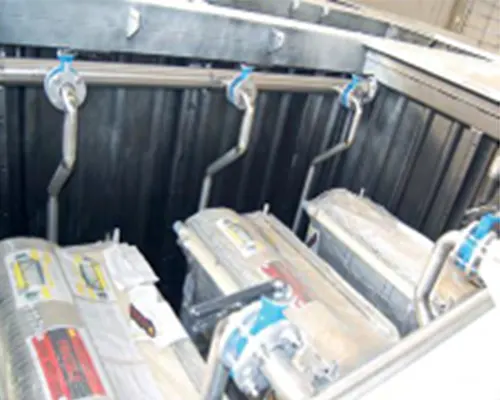
Operation :- Sludge treatment Excess sludge coming from the sludge pump is sent to a dewatering unit. This unit is normally composed of draining bags placed inside a steel structure that allows to reach 15-30% of dried solids content after only an hour, up to 50-80% after storage and dehydration. When the sludge contained in the drainage bags reaches the desired concentration of water, it can be removed, closed and disposed of. The drained water is collected and fed through an external pump at the head of the wastewater treatment plant.
| TECHNICAL DATA | |||||||
|---|---|---|---|---|---|---|---|
| DESCRIPTION | UNITS OF MEASUREMENT | MODEL | |||||
| EMBR 75 | EMBR 100 | EMBR 150 | EMBR 250 | EMBR 500 | EMBR 750 | ||
| Population equivalent, AE | N. | 75 | 100 | 150 | 250 | 500 | 750 |
| Daily flow, Qd | m³/d | 15 | 20 | 30 | 50 | 100 | 150 |
| BOD 5 | kg/d | 4,05 | 5,4 | 8,1 | 13,5 | 27 | 40,5 |
| Membrane surface | sq. | 22,5 | 45 | 90 | 180 | 360 | 540 |
| Membrane Modules | N. | 1 | 1 | 1 | 2 | 4 | 4 |
| Container type | N. | 1×20′ | 1×20′ | 1×40′ | 1×40′ HC | 2×40′ HC | 2×40′ HC |
| Pipe diameter in / out | DN | DN 80 | DN 80 | DN 100 | DN 100 | DN 150 | DN 150 |